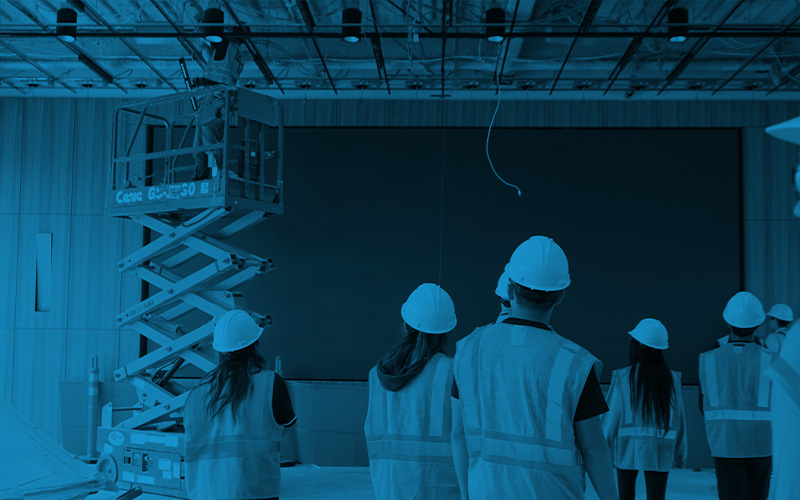

Invisible by Design: Key Insights from InfoComm 2026
Explore TEECOM’s key takeaways from InfoComm 2026, including AI, AV integration, smarter collaboration, and technology designed...
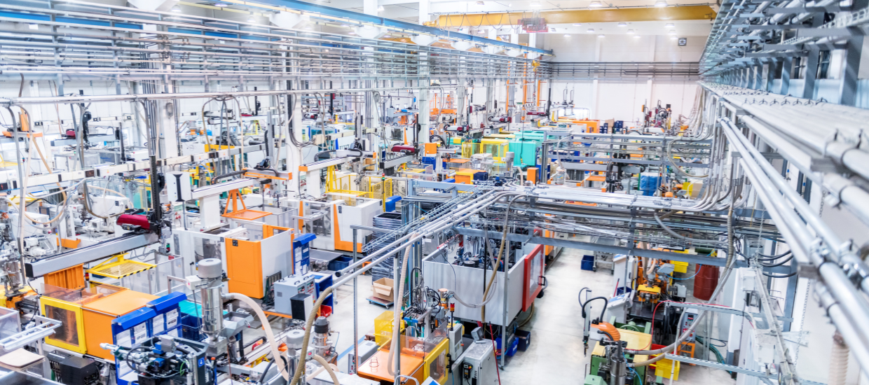
High-volume manufacturing facilities, especially those supporting semiconductor fabrication, are built to operate for decades. However, they rarely remain static. These facilities often undergo significant changes following the base build, with equipment footprints expanding, process nodes shifting, and system requirements increasing far beyond initial projections. What begins as a carefully coordinated facility quickly becomes constrained without thoughtful planning for future evolution.
To keep pace with this change, future-proofing is essential. At TEECOM, we specialize in designing infrastructure including telecom, wireless, and life safety systems that can adapt to both known and unforeseen needs. This adaptability enables facilities to remain operationally efficient, safe, and technologically relevant well into the future.
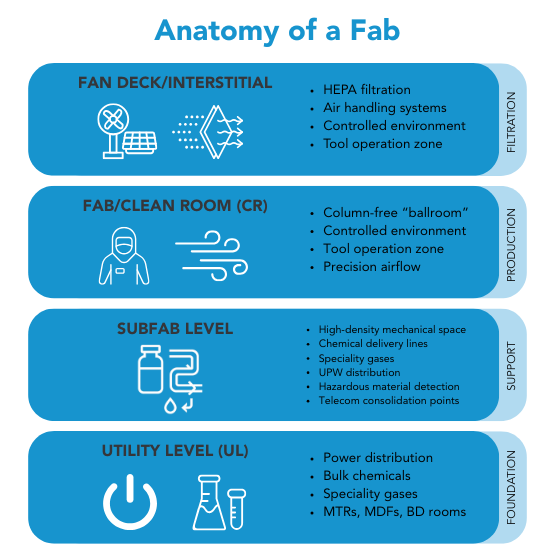
To future-proof a high-volume manufacturing facility, one must first understand the physical and functional structure of a semiconductor fab. These facilities are layered, with each level playing a distinct and critical role.
The Utility Level (UL) is the ground floor and serves as the source point for all building systems. This level houses major utilities such as power distribution, bulk chemicals, specialty gases, and critical telecom infrastructure like MTRs, MDFs, and BD rooms. A typical fab contains two MDFs. Life safety systems and instrumentation and control (I&C) rooms are also located here. It is this level that feeds all other systems in the building, setting the foundation for operational continuity.
Above the UL is the subfab level, where the real complexity begins. The subfab is designed to support cleanroom operations and tool installations, and it is one of the most densely packed environments in the facility. This level contains numerous chemical supply lines, gravity drains, specialty gas delivery systems, life safety equipment (including hazardous production material detection), telecom consolidation points, ultra-pure water (UPW) systems, vacuum piping, and various mechanical air supplies such as argon, hydrogen, nitrogen, and oxygen. The subfab supports the cleanroom above and must accommodate significant systems in extremely tight quarters, often with little room for future additions.
At the core of the facility is the FAB or Clean Room (CR). This space is column-free and often referred to as a “ballroom” due to its open, expansive nature. It is here that semiconductor production takes place under highly controlled environmental conditions. Above the cleanroom is the fan deck or interstitial, which houses HEPA filters and air handling systems. These systems push filtered air downward through the cleanroom and return it through the sides, maintaining the strict airflow and cleanliness standards required for chip fabrication.
Using proper terminology, such as utility level, subfab, CR, and fan deck, not only ensures clarity but also demonstrates the specialized knowledge needed to coordinate effectively across disciplines within this environment.
One of the biggest future-proofing challenges is anticipating how a facility’s systems will need to grow as production evolves. Process advancements, such as shifts in lithography nodes, rarely bring linear increases in infrastructure requirements. A seemingly minor upgrade from one process node to another can create outsized demands on the physical and technical systems supporting the factory.
For instance, a facility may originally be designed to accommodate three argon skids to support its current process. However, as new tools or process nodes are introduced, this number could increase to seven. With space already at a premium and infrastructure pathways fixed during the initial build, adding four additional skids becomes a serious challenge. In these cases, the inability to accommodate growth without major rework reflects a failure to design for future flexibility.
TEECOM helps clients plan for such possibilities by integrating scalable infrastructure strategies. These include distributed consolidation points, adaptable telecom outlet layouts, and redundant source paths that allow additional systems to be brought online with minimal disruption. By accounting for nonlinear growth, we help extend the operational life and efficiency of each facility.
Future-proofing is not limited to mechanical or chemical systems. Scalable information and communications technology (ICT) design is equally important in keeping a facility competitive and operationally agile.
Legacy thinking often favours hardwiring telecom outlets to every piece of equipment, even when voice lines are no longer needed. While dependable, this approach lacks flexibility. In contrast, more forward-thinking clients are adopting distributed patching architectures, consolidation points, and Wi-Fi-based IoT integrations. These approaches allow for dynamic monitoring, simplified maintenance, and rapid tool changes without pulling new cable for each change.
Another key advantage of a CP-heavy design is its long-term cost efficiency. Once a basebuild facility design is released for construction, multiple layout-dependent packages are issued, and the cost of adding new telecom outlets post-design increases significantly—often ranging from $2,500 to $5,000 per outlet. This spike is due to the complexity and congestion of the built environment. At that point, scattered scaffolding is often required for complex conduit routing, where installation crews are often installing one or two outlets in random locations. A robust CP strategy helps mitigate this by providing flexible, pre-positioned access points that reduce the need for costly, labor-intensive retrofits down the line.
TEECOM supports these flexible design strategies by delivering modular, scalable network infrastructure. Our approach enables easy device onboarding, reconfigurable production lines, and robust support for evolving toolsets. The result is an ICT system that evolves with the facility, rather than holding it back.
In facilities that handle volatile chemicals and gases, safety regulations directly influence how connectivity systems are deployed. Areas classified under Class 1, Division 2 and outlined by Article 500 of the National Electrical Code (NEC) must follow strict guidelines to avoid ignition risks from electrical equipment.
Wireless systems in these spaces must be designed with extreme care. Devices cannot be placed within certain classified zones unless properly enclosed in explosion-proof housings. In many cases, wireless access points and DAS antennas must be positioned outside the hazardous zone boundaries or within sealed enclosures to meet code compliance.
TEECOM designs wireless and DAS systems with a safety-first approach. We understand how classification bubbles, encased zones, and code requirements shape deployment options. By addressing safety constraints from the outset, we ensure that connectivity can be delivered without compromising compliance or worker well-being.
Future-proofing does not end with technical design. It also depends on tight coordination among all trades throughout design and construction. From conduit runs to standing equipment, every element of the facility must be carefully planned, signed off, and integrated with adjacent systems. Even small details, such as placing a junction box on a column or a camera above a doorway, require approval from the client’s industrial engineering team, often to the exact inch.
Telecom, in particular, must be integrated across all disciplines. It serves as the backbone for system monitoring, access control, life safety, and tool operation. Delays or misalignment in telecom design can ripple across the project and cause major disruptions.
At TEECOM, our interdisciplinary coordination process ensures that every telecom element is accounted for and aligned with mechanical, electrical, chemical, and safety systems. We produce clear documentation, participate in design reviews, and anticipate downstream impacts. This level of integration is essential for delivering a truly future-proofed facility.
High-volume manufacturing facilities represent some of the most complex environments in the built world. Designing them to evolve over time is not just a technical preference, it is a strategic imperative.
A future-proofed facility balances three core needs: technical flexibility, code compliance and hazard mitigation, and seamless coordination across disciplines. At TEECOM, we deliver all three. Our expertise in telecom/ICT, wireless, and safety-driven design positions us as a trusted partner in helping clients navigate the long life and rapid change of manufacturing facilities. Contact us to learn more about how TEECOM supports the manufacturing and industrial market.
John Hurson is a telecom designer with more than 15 years of experience delivering advanced technology solutions for some of the world’s most complex projects. Known for his ability to balance speed and precision, John has led both fast-track and long-term engagements, guiding clients through critical design decisions with clarity and care. He believes that the smallest details often have the biggest impact, and he brings that mindset to every project he supports.
Stay ahead of the curve with our latest blog posts on industry trends, thought leadership, employee stories, and expert insights.